3D printer
A 3D printer is as expensive as you make it–my goal was to make a cheap, reasonably-sized 3D printer that I could use at home.
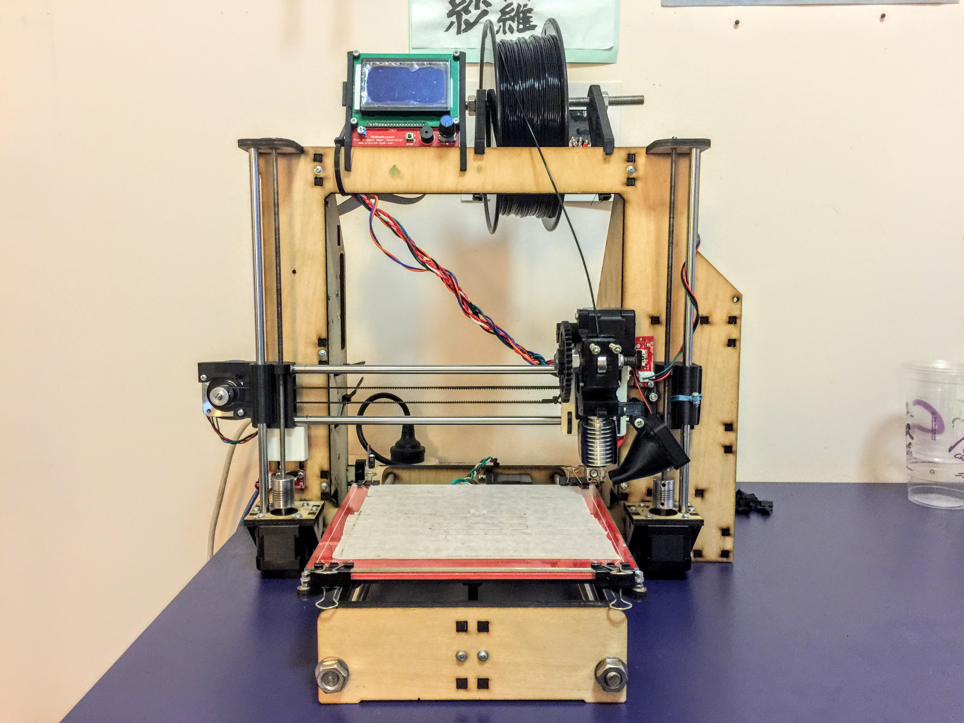
The maximum build volume of the printer is 200 mm x 200 mm x 150 mm. It’s based on the Prusa i3 and controlled by a RAMPS 1.4 board with a RepRapDiscount Full Graphic Smart Controller attached for screen and SD card functionality. An ATX power supply from an old PC was used as the power source.
The frame
The original version of this printer is designed to use as little panel parts as possible, opting for 3D-printed parts instead, adhering to the RepRap philosophy. But since I had access to a laser cutter I tried to replace as many of the 3D printed parts as I could.
As such, parts such as the stepper motor mounts, power supply enclosure, y-axis front and back, and the y-idler, are all laser-cut out of 6 mm ply. This is in addition to the main vertical frame and the print bed mount. Laser cutting files can be cound at the bottom of the page.
Using laser-cut parts greatly sped up production time as 3D printing is a very slow process, added onto the fact that I was sharing printer time with other pupils. There is no glue used in the construction of the frame as it instead uses captive T-slot nuts to assemble the pieces.

Motion mechanisms
There are two mechanisms used to convert the stepper motor circular motion into linear motion. For the x- and y-axes, a GT2 timing belt is attached to the stepper motor and the moving mass (extruder and print bed). The motor shaft has a pulley fixed to it in order to move the belt with precision. On the opposite side of each axis there is a linear bearing to support the belt.

To attach the mass to the belt, the belt is looped around a 3D printed part and zip-tied in place. Due to the shape of the belt, this is sufficient to hold it very securely in place. It should be noted that the belt is only for transferring motion; the actual mass is supported by linear bearings running along smooth stainless steel rods.

For the z-axis where precision is more important than speed, the motor shaft is coupled to a 5 mm threaded rod. M5 nuts are embedded into the 3D printed parts that comprise the z-axis, allowing the z-axis to move via screw action.

The extruder
The extruder is the section that melts the plastic filament and deposits it onto the print bed. It can be split up into two halves.
The top half comprises the carriage mount that attaches it to the two horizontal steel rods, a stepper motor that feeds the filament at a controlled rate, and a guide that directs the filament downward. It also features a spring-loaded mechanism to easily remove and swap filaments.

The bottom half is the hotend. The one I’m using is a cheap clone of the E3D V5. There are two fans on the hotend: one cools the plastic as it prints and the other siphons heat from the heatsink before it can reach the upper plastic portion of the extruder. I’ve only ever tried printing PLA plastic with this printer, but in theory it should work with ABS too.

The print bed
The print bed is a fairly standard PCB Heatbed. It’s attached on top of a mount that runs along two steel rods using linear bearings and is pulled along by a GT2 timing belt.
A piece of borosilicate glass is clipped to the top of the heatbed. I’ve tried a number of different bed adhesion techniques including Kapton tape, glue and hairspray, but I’ve found that masking tape does the best job of keeping parts stuck down without making them impossible to remove.

The electronics
An ATX power supply powers the entire setup. It is encased within a laser-cut enclosure behind teh right side of the frame. A hole in the top gives access to the mains plug and power switch. To break out the 12V and GND lines I mutilated an ATX power cord and bundled the related wires together. The remaining wires are tucked away in a small section underneath the power supply.

The RAMPS 1.4 board is mounted on the left side of the 3D printer. The power supply cables go underneath the printer and come out through a hole at the bottom of the left panel. Here, it joins the messy jumble of wires at include cables for the endstops, heated bed, stepper motors and thermistors all joining up to the controller board.

The screen is a RepRapDiscount Full Graphic Smart Controller which attaches to the RAMPS board via two ribbon cables. In addition to a controller knob and a piezo buzzer, it has an SD card slot on the side that allows printing without a computer. As I often leave the printer running when I’m out of the house, this has provend itself to be an indispensable feature.

Final comments
This writeup glosses over a lot of stuff about the printer but I hope it’s enough to give a basic overview. I found that what matters most in 3D printing is not so much the components you use (though that helps a lot), but the countless hours taken to adjust and refine the methods, settings and materials used. The slicer also makes a huge difference–I’m using Simplify3D.
Having a 3D printer has been more fun and useful than I could have expected. Once you get into the mindset that everything can be solved with a 3D printer, the opportunities are endless–from table leg extensions and 3D printer parts to Eiffel Towers and kazoos. You can do it all with a 3D printer.